Hands-on with HDMI 2.1 + VCU2 Reference Design on AMD VEK385
As video systems evolve from 4K60 toward 8K, high frame rates, high color depth, and low latency, the traditional "FPGA + external video processing chip" architecture faces increasing challenges in system complexity, bandwidth, power consumption, and software adaptation.
The AMD Versal Gen 2 platform features a more highly integrated design across PS, PL, NoC, DDR, GT, high-speed video interfaces, and hard video processing units. This article, based on the HDMI 2.1 + VCU2 reference design on the VEK385 platform, introduces Versal Gen 2 device capabilities, VCU2 architecture, HDMI video chain, and the compilation and operation of the reference design.
1 Versal Gen 2 Device Overview
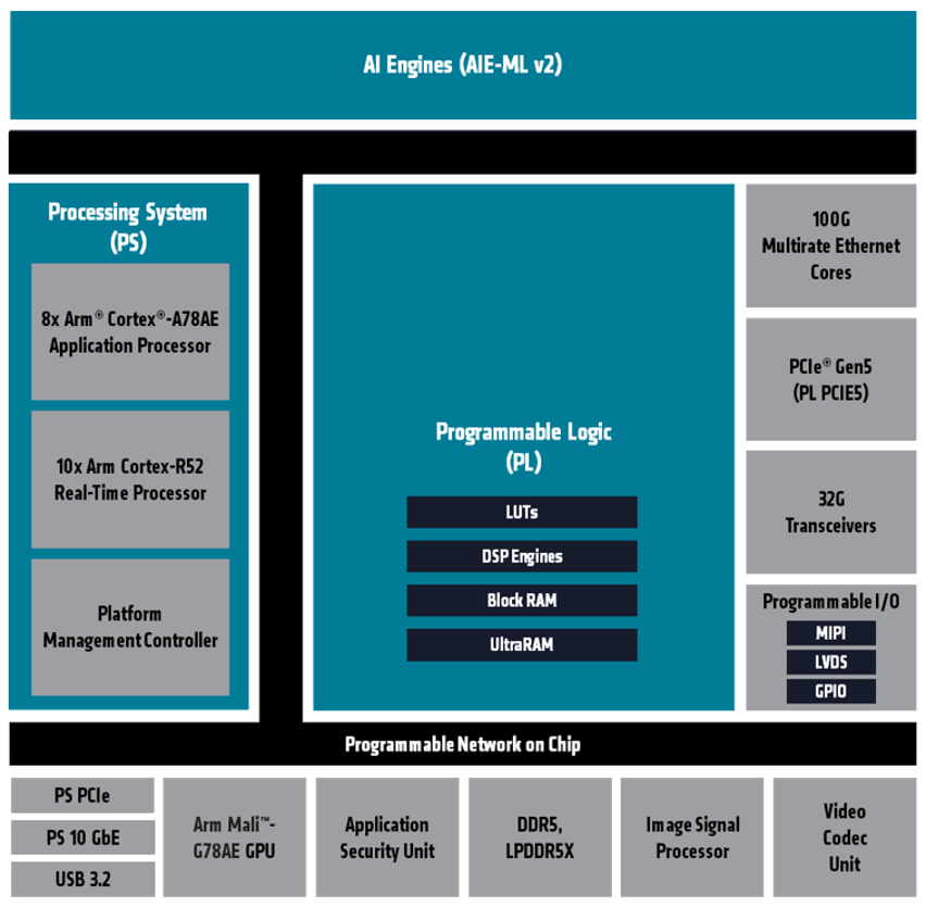
Versal Gen 2 Architecture
Versal Gen 2 is AMD's Adaptive SoC for next-generation embedded computing and video processing scenarios. Compared with first-generation Versal, Versal Gen 2 delivers significant enhancements in several areas:
First, processor performance is stronger. The Gen 2 platform provides higher-performance APU and RPU, integrating up to 8-core Arm Cortex-A78 and 10-core Arm Cortex-R52, delivering greater compute capability and suitable for running more complex Linux applications, driver frameworks, and control tasks.
Second, AI Engine capability is improved. The new-generation AI Engine in AI Edge Gen 2 supports higher-energy-efficiency AI inference and also supports new data types such as MX6 and MX9, making it suitable for edge AI, vision recognition, and signal processing applications.
Third, video processing capability is more complete. Versal Gen 2 integrates a hard ISP and VCU, where the ISP can be used for image signal processing and the VCU/VCU2 can be used for video encoding and decoding.
Fourth, high-speed interface and memory capabilities are stronger. The device integrates high-speed PS interfaces such as PCIe Gen5, 10G Ethernet, USB 3.2, DisplayPort, and UFS; it also supports DDR5 and LPDDR5X and enables high-bandwidth data access between modules through NoC.
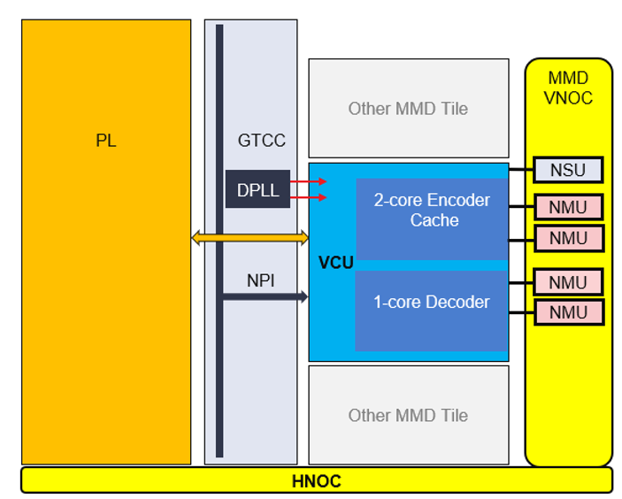
VCU2 Architecture
VCU2 is the hard video codec unit in the Versal Gen 2 platform. VCU2 supports H.264 and H.265 encoding and decoding, as well as JPEG decoding; color formats support 40, 42, 44, and Monochrome; color depth supports 8-bit, 10-bit, and 12-bit. A single VCU2 Tile supports 4Kx2Kp60 encoding and 4Kx2Kp60 decoding, and supports Frame Buffer Compression, multi-stream, and hardened encoding cache.
Compared with the VCU in the Zynq UltraScale+ MPSoC EV series, the changes in VCU2 are mainly reflected in the following aspects.
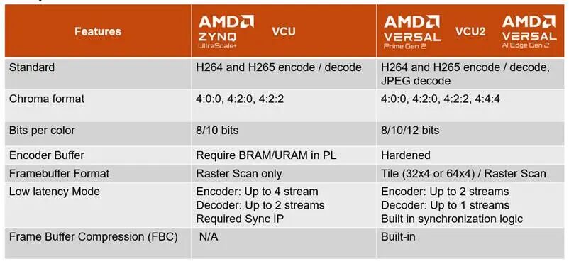
As can be seen, the improvements in VCU2 are not single-point enhancements but overall optimization around high-resolution, high-color-depth, high-bandwidth, and low-latency video systems. In particular, hardened encoding cache, Tile format, FBC, and 44/12-bit support are critical for high-quality video processing chains.
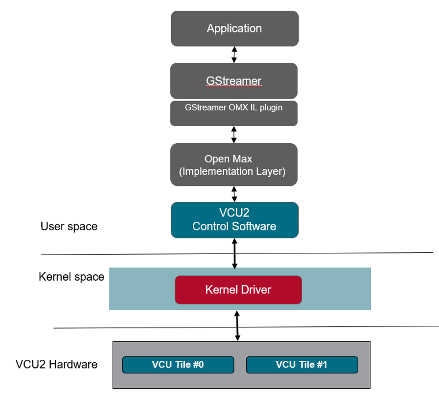
VCU2 Software Architecture
From a software architecture perspective, VCU2 does not expose bare hardware directly to the application layer. A typical software path can be understood as: GStreamer application layer -> OpenMAX -> VCU2 Control Software -> Kernel Driver -> VCU2 Hardware.
For application engineers, GStreamer is the most commonly used. It can chain video input, format conversion, encoding, decoding, and display through a Pipeline. VCU2 Control Software is responsible for lower-level frame-level or slice-level control, such as generating or parsing NAL units, submitting commands to firmware, obtaining per-frame status, and concatenating bitstreams.
Therefore, in the VEK385 HDMI + VCU2 reference design, we do not directly manipulate the VCU2 registers; instead, we debug the entire video pipeline through software frameworks such as the Linux driver, V4L2, DRM/KMS, and GStreamer.
3VEK385 HDMI 2.1 + VCU2 Reference Design Overview
The goal of the VEK385 HDMI 2.1 + VCU2 reference design is to run a complete video input, processing, codec, and output pipeline on the VEK385 platform.

HDMI Advanced Subsystem Design
The basic video path of the reference design can be understood as: HDMI video source -> HDMI RX -> VPSS -> Frame Buffer -> DDR -> VCU2 codec -> Frame Buffer -> HDMI TX -> monitor.
The video received by HDMI RX is not directly looped back to HDMI TX; instead, it passes through the VPSS, Frame Buffer, DDR, and VCU2 codec pipeline before being output via HDMI TX. This path is closer to real video applications, such as video capture, format conversion, encoding, decoding, and display.
The overall build and workflow of the HDMI 2.1 + VCU2 reference design are shown in the figure below:
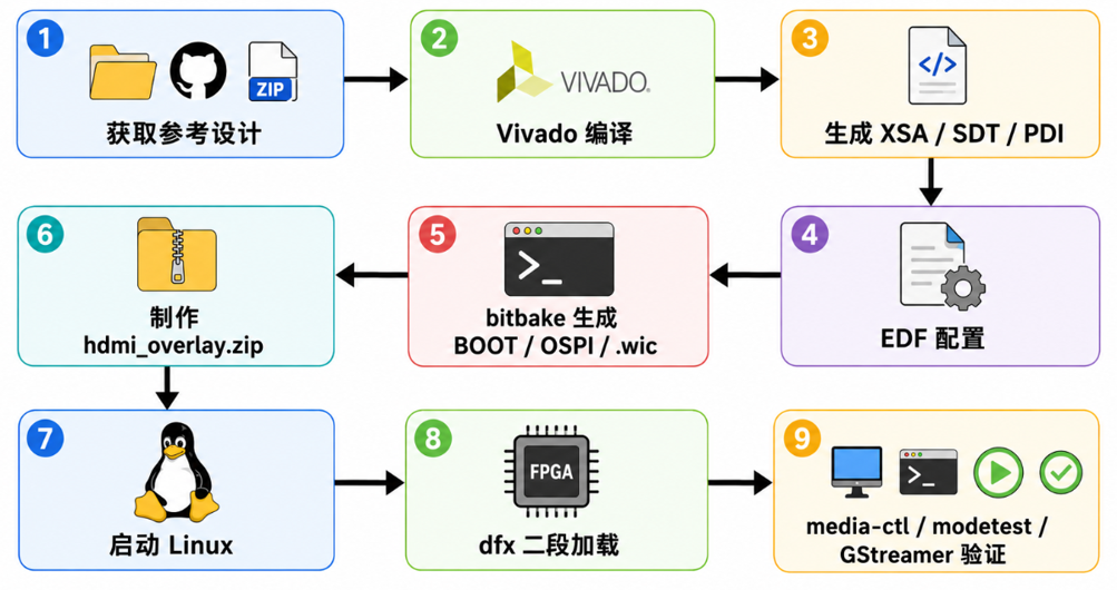
On the host side, complete the reference design source code retrieval, Vivado hardware build, EDF configuration, and bitbake image generation; at the same time, create hdmi_overlay.zip based on SDT / PDI; after the board boots Linux, load the overlay via dfx-mgr-client and verify the HDMI + VCU2 pipeline using media-ctl, modetest, and GStreamer.
The reference design project can be obtained from Xilinx GitHub. On Windows, you can directly download the ZIP package; on Linux, you can use git clone.
git clone https://github.com/Xilinx/versal2-vek385-advss.git
After downloading and extracting, enter the hdmi reference design folder, and you will see the file structure shown in the figure below.
The HDMI reference design directory contains directories or files such as hw, scripts, xdc, sw, and Makefile. Among them, hw is used for the Vivado hardware project, scripts contains the main Tcl scripts, xdc is used for constraints, and sw is used for EDF software build.
4.2 Vivado Build of the Hardware Design
Enter the HDMI hardware project directory, load the Vivado 2025.2 environment variables, and then run the build.
cd /home/vek385/vek385/workspace/hdmi/versal2-vek385-advss-2025.2/hdmi/hw source /opt/xilinx/2025.2/Vivado/settings64.sh make all
This step completes Vivado project creation, synthesis, implementation, bitstream / PDI generation, and generates the hardware description files required for subsequent EDF parsing.
After the build is complete, the hdmi.xsa file is generated under the hw/runs/hdmi path. In practice, it is important to confirm that the Vivado version matches the reference design branch; for example, when using the 2025.2 branch, it is recommended to use the Vivado 2025.2 environment to avoid errors caused by version mismatch.
4.3 EDF Build of the Linux Image
After the Vivado build is complete, enter the software directory and load the EDF Yocto build environment.
cd /home/vek385/vek385/workspace/hdmi/versal2-vek385-advss-2025.2/hdmi/sw source /opt/yocto/edf_v25.11/edf-init-build-env
Then modify build/conf/local.conf to add the download directory, sstate cache, parallel build parameters, and HDMI 2.1 driver module.
DL_DIR = "/opt/yocto/downloads" SSTATE_DIR = "/opt/yocto/sstate-cache" PARALLEL_MAKE = "-j 32" BB_NUMBER_THREADS = "32" IMAGE_INSTALL:append = "kernel-module-hdmi21" BB_NO_NETWORK = "1"
Among these, IMAGE_INSTALL:append = "kernel-module-hdmi21" is critical; otherwise, the HDMI 2.1-related driver modules may be missing after system boot.
Next, use gen-machineconf to generate the machine configuration and device tree based on the SDT / hardware description output by Vivado.
MACHINE=versal-2ve-2vm-vek385-revb-sdt-seg gen-machineconf parse-sdt --template /opt/yocto/edf_v25.11/sources/meta-amd-adaptive-socs/meta-amd-adaptive-socs-bsp/conf/machineyaml/versal-2ve-2vm-vek385-revb-sdt-seg.yaml --hw-description /home/vek385/vek385/workspace/hdmi/hw/hdmi_sdt --machine-name versal-2ve-2vm-vek385-revb-sdt-seg
The --hw-description path here needs to be adjusted according to the actual output directory of Vivado / sdtgen mentioned earlier. Then build the OSPI boot image and the EDF Linux filesystem image.
MACHINE=versal-2ve-2vm-vek385-revb-sdt-seg bitbake edf-ospi MACHINE=amd-cortexa78-mali-common bitbake edf-linux-disk-image
After the build completes, you will typically obtain key files such as edf-ospi-*.bin, BOOT-*.bin, and edf-linux-disk-image-*.wic.xz. The .wic.xz can be used to flash an SD card, while BOOT.bin or the OSPI boot image is used for booting.
The SD card image can be flashed using tools such as balenaEtcher. Select the generated .wic or .wic.xz image and write it to a 16GB / 32GB Micro-SD card.
After flashing is complete, insert the SD card into the VEK385. Choose the boot method according to your actual debugging strategy: if booting from the default OSPI image, confirm the board's boot mode DIP switch settings;
The Versal Gen 2 reference design uses a two-stage loading approach. The system first boots the PS, DDR, and basic NoC through the first-stage PDI, and after Linux starts, it loads the PLD PDI and device tree overlay.
When creating the two-stage loading files, three core files need to be prepared: pl.dtbo, XXX_pld.pdi, and shell.json. Among them, pl.dtbo comes from the compiled result of the modified pl.dtsi, XXX_pld.pdi comes from the Vivado / sdtgen output directory, and shell.json is used to describe the shell type and slot information.
It is necessary to add or modify HDMI-related nodes in pl.dtsi, add the ref40m fixed-clock, add the xv_fmc connector node, modify the hdmi_ss_axi_iic node, modify the clock-names and clocks references of the hdmi_gt_controller node, and modify the max-bits-per-component property of the HDMI RX Subsystem.
Then use dtc to compile the device tree overlay. After compilation, the pl.dtbo device tree file will be generated in the path.
dtc -I dts -O dtb -@ -o pl.dtbo pl.dtsi
Create an overlay directory and place pl.dtbo, the second-stage PDI, and shell.json into it.
mkdir hdmi_overlay cp pl.dtbo hdmi_overlay/ cp XXX_pld.pdi hdmi_overlay/
An example of the shell.json content is shown below.
{ "shell_type" : "XRT_FLAT", "num_slots" : "1" }
Finally, compress it to obtain hdmi_overlay.zip.
zip -r hdmi_overlay.zip hdmi_overlay/
4.6 Booting the HDMI+VCU2 Function
After Linux boots, place hdmi_overlay.zip in the designated location on the board, then perform the second-stage loading.
dfx-mgr-client -load hdmi_overlay
After successful loading, the Linux system should be able to recognize HDMI, Video, DRM/KMS, VCU2, and other related device nodes. First, you can use media-ctl to view the video input topology.
Then configure the VPSS input and output formats. The following commands come from the reference design materials. In actual use, adjustments need to be made according to the entity names, resolutions, and formats printed by media-ctl -p.
media-ctl -d /dev/media0 -V '"b0000000.v_proc_ss":0 [fmt:RBG888_1X24/3840x2160 field:none]' media-ctl -d /dev/media0 -V '"b0000000.v_proc_ss":1 [fmt:VYYUYY8_1X24/3840x2160 field:none]'
Next, use modetest to view the DRM/KMS output device and set the HDMI TX output mode, for example 4K60.
modetest -D axi:drm-pl-disp-drvhdmi_ss_hdmi_tx_ss_v_hdmi_txss1 modetest -D axi:drm-pl-disp-drvhdmi_ss_hdmi_tx_ss_v_hdmi_txss1 -s 39@35:3840x2160-60@BG24
Finally, HDMI input, VCU2 encoding, VCU2 decoding, and HDMI output can be completed through GStreamer.
gst-launch-1.0 v4l2src device=/dev/video0 io-mode=4 ! video/x-raw, width=3840, height=2160, format=NV12, framerate=60/1 ! omxh265enc qp-mode=auto gop-mode=basic gop-length=60 b-frames=0 target-bitrate=60000 control-rate=constant prefetch-buffer=true low-bandwidth=false ! video/x-h265, profile=main, alignment=au ! queue ! omxh265dec internal-entropy-buffers=5 low-latency=0 ! queue max-size-bytes=0 ! fpsdisplaysink name=fpssink text-overlay=false fps-update-interval=1000 video-sink="kmssink driver-name=xlnx plane-id=33 show-preroll-frame=false" -v
The purpose of this command can be simply understood as: V4L2 captures HDMI input -> specify raw video format -> H.265 encoding -> H.265 decoding -> KMS display output. That is, using GStreamer to chain input, encoding, decoding, and display into a complete video processing pipeline.
The value of the VEK385 HDMI 2.1 + VCU2 reference design lies in the fact that it is not a standalone HDMI demo, nor a standalone VCU2 demo, but a complete video system reference chain.
From a hardware perspective, it covers HDMI RX, GT, VPSS, Frame Buffer, NoC, DDR, VCU2, and HDMI TX. From a software perspective, it covers EDF Linux, device tree overlay, DFX two-stage loading, V4L2, DRM/KMS, and GStreamer.
From an engineering hands-on perspective, after getting this design running, developers can master several core methods of the Versal Gen 2 video system: how to build the HDMI 2.1 input and output chain, how to organize video frame data through NoC and DDR, how to use VCU2 for hardware encoding and decoding, how to debug the video pipeline through the Linux multimedia framework, and how to use the two-stage loading method to load PL functions and device tree overlays.
For engineers who subsequently work on video capture, video transcoding, edge video processing, high-definition display, industrial vision, or low-latency video transmission systems, this reference design is a highly valuable starting point.
Avnet is a leading global technology distributor and solutions provider that has remained true to its founding purpose for more than a century, committed to meeting customers' evolving needs. Through specialized and regional business coverage across the globe, Avnet supports customers and suppliers at every stage of the product lifecycle. Avnet helps companies of all types adapt to changing market conditions and accelerate design and supply during product development. Avnet sits at the center of the entire technology supply chain, and this unique position and perspective make it a trusted partner that can help customers solve complex design and supply chain challenges and achieve revenue faster. To learn more about Avnet, please visit www.avnet.com
Original title: AMD Technical Insights | Hands-on with HDMI 2.1 + VCU2 Reference Design on AMD VEK385
How to complete end-to-end inference on the VEK385 development board using pre-compiled models
AMD VEK385 LPDDR5X-8533 Performance Test
How to solve no output from HDMI on dm 385?
Definition of the HDMI 2.1 standard and its differences from HDMI 2.0
What are the differences between HDMI 2.1 and HDMI 2.0
How to distinguish HDMI 2.1 from HDMI 2.0